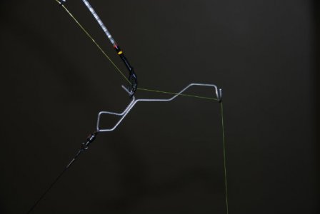
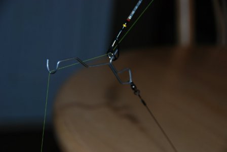
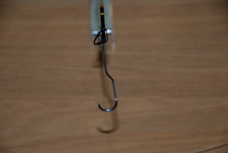
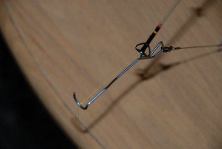
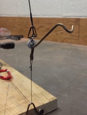
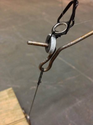
I can't take credit for this device, I got the instructions for it from a gentleman off of another website. Good old copy and paste from a email he sent me.
The length of your ice rod will determine the length of the middle leg. Basically, for a 25 to 28 inch rod my design should suffice. You might want to experiment just a little though if you are using something longer or shorter. It will most likely work just fine but it's always worth improving! I used 3 feet of 3/4" aluminum trim channel. 5/8" would work if you wanted to go slightly smaller but some dimensions would have to be adjusted. I also used button socket cap screws so that they would have a low profile and you can insert a hex key bit into them for tightening inside of the PVC elbow. All the hardware is stainless but that was just my preference.
Here is the materials list:
1. 3ft of 3/4" aluminum trim channel
1. 1/16"x12" stainless steel rod
4. 1/4x3/4" stainless button cap screws and matching lock nuts
2. #10x1/2" stainless button cap screws and matching lock nuts
2. 1x1/2 stainless brace
1. 4.5"x2"x1/8" flat aluminum stock
2. 1/4" nylon fender washers
1. 1" schedule 40 SxS 45 degree PVC elbow
1. 3.5" thin walled drinking water PVC pipe
1. 6"x30lb wire leader with ball bearing and snap swivel
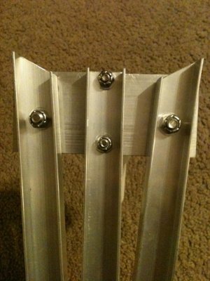
The main aluminum channel is cut to 16.5" and then the ends are sanded to take away any burrs. The hole for the leader and trigger is centered and drilled 1/4" from the end with a 9/64th bit. The end of one leg was cut at an angle of 31.5 degrees. I sanded down the far end of the angle so that the aluminum didn't come to a point but was blunt or flat. Hope that makes sense. Then the leg was then cut to 9" total from the furthest point of the angle to the end of the leg. Another leg was made and the angle was reversed so that I had mirror images of the legs, one for the left and one for the right side. Holes were drilled in the legs exactly 1.5" from the furthest tip of the angle and centered with a pilot bit of 1/8" to 3/32" and then finished with the 1/4" bit. All holes were gently beveled by hand to remove any burrs.
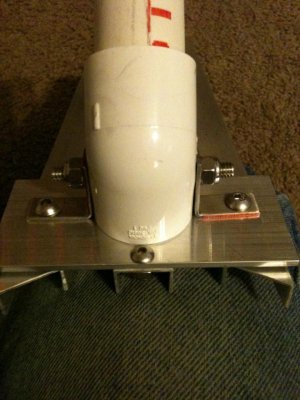
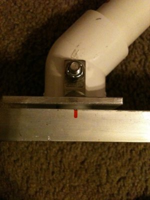
The aluminum plate (flat stock) is cut to 4.5x2" and the elbow is placed in the center and at the furthest forward edge possible. one of the smaller screws is drilled to fit behind the elbow and one is drilled to fit under the elbow. These two screws hold the center channel in place. The flat stock is placed at a 90 degree angle to the center channel and carefully used to drill the holes out for the channel and then bolt it in place with the smaller screws. I used a 3/16" drill bit for those after predrilling with the 5/32" bit. Really took my time as the bits will want to "walk".
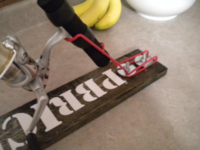
The braces are positioned perfectly on the sides of the elbow and you can even use the mold seam to line them up for drilling. I used bolts that are the exact size of the holes in the braces to keep any wiggle room out of the equation but it requires very accurate hole placement. The larger screws are placed through the holes from the inside of the elbow outward and then the braces are snugged to the sides of the elbow with the lock nuts. I then positioned and centered the elbow on the plate and marked my hole positions and drilled them out first with a pilot hole and then the 1/4" bit. All holes were hand beveled and cleaned up of any burrs.
Then just insert the screws and place a nylon washer between the plate and the leg to aid in folding and unfolding and gently snug up the lock but to hold it in place. Do not over tighten the nut. You only want a little bit of tension on the leg, or you can ad thin nylon washer on befor the nut to sandwich the leg and reduce wear from the nut. After it was assembled I then tightened the screws and nuts that hold the elbow, cut and inserted my piece of pipe to hold the rod and clipped my trigger to the wire leader and the leader to the center channel.
A few tips on bending the wire trigger. I only used 6" of rod to make each trigger but they came in 12" lengths. I went through about 3 rods before I got really good at it! lol The part of the trigger that is inserted into the eye of the rod is 1/2" long and everything else is fairly dimensional after that. I will take a lot better pictures and get them posted as soon as I can to clarify all this but this should get you started. Some of the materials will need to be purchased in longer lengths but it shouldn't be to bad. If you are concerned about wear and tear on the eye then insert a zip-tie through the braces that support the eye of the rod and use that to insert the trigger.
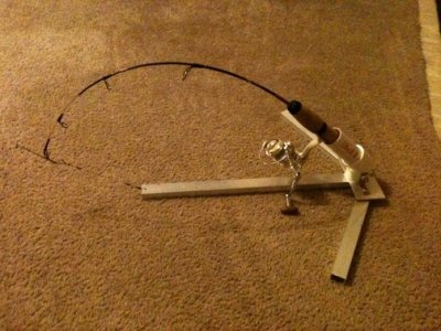
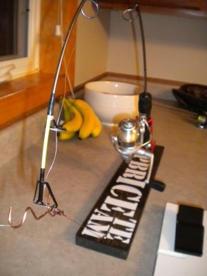
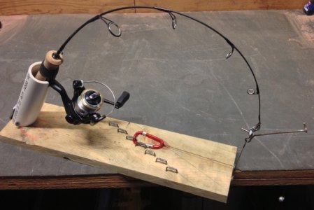
Here are a few pictures of the finished product. If you have questions I will try to answer them. This device is legal in ND, I have a email someplace from NDGF that says so.
Attachments
